Cxlb7285b is an integrated circuit for charging management of two lithium batteries in PWM step-down mode. It can independently manage the charging of two lithium batteries. It has the advantages of small footprint, few peripheral components and simple use. With trickle, constant current and constant voltage charging modes, cxlb7285b is very suitable for lithium battery charging management. In the constant voltage charging mode, the cxlb7285b modulates the battery voltage to 8.4v, which can also be adjusted upward through an external resistance; in the constant current charging mode, the charging current is set through an external resistance. For deep discharge lithium batteries, when the battery voltage is low
At 66.5% (typical) of the constant voltage charging voltage, cxlb7285b uses 17.5% of the set constant current charging current to trickle charge the battery. In the constant voltage charging stage, the charging current decreases gradually. When the charging current decreases to 16% of the constant current charging current, the charging ends. At the end of charging state, if the battery voltage drops to 95.5% of the constant voltage charging voltage, a new charging cycle will start automatically. When the input power is off or the input voltage is lower than the battery voltage, the cxlb7285b will automatically enter the sleep mode.
-
[ CXLB7285B ]"
目录
产品概述 返回TOP
CXLB7285B是PWM降压模式两节锂电池充电管理集成电路,
独立对两节锂电池充电进行管理,具有封装外形小,外围元器件少和
使用简单等优点。CXLB7285B 具有涓流,恒流和恒压充电模式,非常
适合锂电池充电管理。在恒压充电模式,CXLB7285B将电池电压调制
在 8.4V,也可以通过一个外部电阻向上调整;在恒流充电模式,充电
电流通过一个外部电阻设置。对于深度放电的锂电池,当电池电压低
于恒压充电电压的66.5%(典型值)时,CXLB7285B用所设置的恒流充
电电流的17.5%对电池进行涓流充电。在恒压充电阶段,充电电流逐
渐减小,当充电电流降低到恒流充电电流的16%时,充电结束。在充
电结束状态,如果电池电压下降到恒压充电电压的95.5%,自动开始
新的充电周期。当输入电源掉电或者输入电压低于电池电压时,
CXLB7285B自动进入睡眠模式。其它功能包括输入低电压锁存,电池
端过压保护和充电状态指示等。
CXLB7285B 采用 10 管脚 SSOP 封装。
产品特点 返回TOP
宽输入电压范围:6.6V 到 30V
对两节锂电池完整的充电管理
充电电流可达 4A
PWM 开关频率:300KHz
恒压充电电压可用电阻向上调整
恒压充电电压精度: ±1%
恒流充电电流由外部电阻设置
对深度放电的电池进行涓流充电
自动再充电功能
充电状态和充电结束状态指示
软启动功能
电池端过压保护
工作环境温度:-40℃ 到 +85℃
采用 10 管脚 SSOP 封装
产品无铅,满足 Rohs,不含卤素
应用范围 返回TOP
手持设备
备用电池应用
便携式工业和医疗仪器
电动工具
独立电池充电器
技术规格书(产品PDF) 返回TOP
需要详细的PDF规格书请扫一扫微信联系我们,还可以获得免费样品以及技术支持!

产品封装图 返回TOP

|
管脚序号 |
名称 |
说明 |
|
1 |
VG |
内部电压调制器输出。为内部驱动电路提供电源,在 VG 管脚和VCC 管脚之间需要接一个 100nF 的电容。 |
|
2 |
GND |
地。输入电源的负输入端和电池负极。 |
|
3 |
CHRG |
充电状态指示端。漏极开路输出。在充电状态,内部晶体管将此管脚拉到低电平;否则,此管脚为高阻状态。 |
|
4 |
DONE |
充电结束指示端。漏极开路输出。在充电结束状态,内部晶体管将此管脚拉到低电平;否则,此管脚为高阻状态。 |
|
5 |
COM |
回路补偿输入端。在此管脚到地之间串联连接一个 120Ω 的电阻和一个 220nF 的电容。 |
|
6 |
FB |
电池电压检测输入端。此管脚用于检测电池正极的电压。如果在FB 管脚和 BAT 管脚之间接一个电阻,可以向上调整恒压充电电压。 |
|
7 |
BAT |
电池正极连接端和充电电流检测负输入端。此管脚连接到电池的正极。同时,此管脚和CSP管脚测量电流检测电阻RCS两端的电压,并将此电压信号反馈给CXLB7285B进行电流调制。 |
|
8 |
CSP |
充电电流检测正输入端。此管脚和BAT管脚测量电流检测电阻RCS两端的电压,并将此电压信号反馈给CXLB7285B |
|
9 |
VCC |
外部电源正极输入端。VCC 也是内部电路的电源。此管脚到地之间需要接滤波电容。 |
|
10 |
DRV |
栅极驱动端。驱动片外 P 沟道 MOS 场效应晶体管的栅极 |
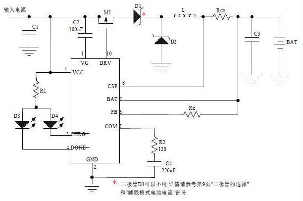
电路原理图 返回TOP
相关芯片选择指南 返回TOP 更多同类产品......
|
外置MOS 2节锂电充电IC |
|||||||||
|
型号 |
电池数量 |
工作模式 |
工作电压 |
最大充电电流 |
工作电流 |
恒流恒压精度 |
输出电压 |
开关频率 |
封装 |
|
两节 |
线性,外置MOS |
9V-18V |
扩流1.5A |
0.25mA |
1% |
8.4V |
SOP-8L |
||
|
两节 |
线性,外置MOS |
9V-12V |
扩流3A |
1mA |
1% |
8.4V |
SOP-8L |
||
|
两节 |
开关式外置MOS |
8.9V-20V |
扩流2A |
1.5mA |
1% |
8.4V |
450KHz |
SOP-8L |
|
|
两节 |
开关式外置MOS |
9.0V-18V |
扩流2A |
5mA |
1% |
8.35V |
400KHz |
TSSOP14 |
|
|
两节 |
开关式外置MOS |
7.5V-28V |
扩流5A |
1.55mA |
1% |
8.4V |
300KHz |
TSSOP16 |
|
|
两节 |
开关式外置MOS |
6.6V-30V |
扩流4A |
1mA |
1% |
8.4V |
300KHz |
SSOP10 |
|


